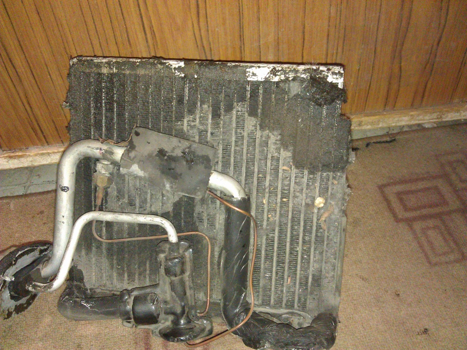
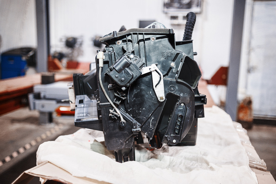
Вот так выглядит корпус печки.
Печка в сборе
Справа к ней прикручен вентилятор и заслонка рециркуляции. В центральном тоннеле две заслонки: одна регулирует температуру, вторая – направление обдува. В самом низу под ними стоят два теплообменника:
– радиатор печки – вставляется слева по ходу движения
– испаритель – стоит на стыке с вентилятором
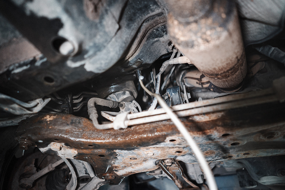
Место установки радиатора печки
Получаем бутерброд из двух радиаторов друг над другом. В зависимости от положения режима обдува мы сможем длинной тонкой трубкой подобраться к одному из них. Логика подсказывает, что нужно выбрать "в лицо" и одну из крайних точек температуры. Распыляем, после чего запускаем кондиционер. Он автоматически начнёт сушит воздух и сливать конденсат через дренажное отверстие. Неплохо бы делать всё на холодной машине, чтобы радиатор печки не мешал нашей красоте и жидкость дошла до испарителя, так как он стоит чуть дальше (память может изменять мне).
Вот выдержка из руководства для Калибра, у вас идентичные печки.
Both the manual temperature control (MTC) heating-A/C system and the heater-only system are blend-air type sys- tems. In a blend-air system, a blend-air door controls the amount of conditioned air that is allowed to flow through, or around, the heater core. The temperature control determines the discharge air temperature by operating the blend door cable, which moves the blend-air door. This design allows almost immediate control of output air tem- perature.
NOTE: Typical blend-air type HVAC system shown.
 Heater.jpg 62,5К
1 Количество загрузок:
Heater.jpg 62,5К
1 Количество загрузок:
The heating-A/C system pulls outside (ambient) air through the cowl opening at the base of the windshield, then into the air inlet housing above the heating, ventilation and air conditioning (HVAC) housing. On models equipped with A/C, the air passes through the A/C evaporator (3). Air flow can be directed either through or around the heater core (1). This is done by adjusting the blend-air door (2) with the temperature control located on the A/C-heater control in the instrument panel. The air flow can then be directed from the panel, floor and defrost outlets in various combinations using the mode control located on the A/C-heater control. Air flow velocity can be adjusted with the blower speed control located on the A/C-heater control.
The outside (fresh) air intake can be shut off by pressing the Recirculation button on the A/C-heater control. This will operate an electrically actuated recirculation-air door (4) that closes off the fresh air intake and recirculates the air that is already inside the vehicle.
The A/C compressor can be engaged by pressing the A/C (snowflake) button on the A/C-heater control. It will auto- matically engage when the mode control is set in any Mix to Defrost position. This will remove heat and humidity from the air before it is directed through or around the heater core. The mode control on the A/C-heater control is used to direct the conditioned air to the selected system outlets. The mode control uses a control cable to operated the mode-air doors (5 and 6).
The defroster outlet receives airflow from the HVAC housing through the molded plastic defroster duct, which is secured to the top of the instrument panel. The airflow from the defroster outlet is directed by fixed vanes in the defroster outlet grille and cannot be adjusted.
The side window demister outlets receive airflow from the HVAC housing through the defroster duct and molded plastic demister ducts. The airflow from the side window demister outlets is directed by fixed vanes in the demister outlet grilles and cannot be adjusted. The side window demister outlet grilles are integral to the instrument panel cover and direct air from the HVAC housing through the outlets on the top corners of the instrument panel. The demisters operate when the mode control is set in any Floor to Defrost position.
The panel outlets receive airflow from the HVAC housing through the center air distribution duct and molded plastic panel outlet ducts. The airflow from each of the panel outlets is adjustable. A thumbwheel located at the bottom of each panel outlet grille is used to adjust a center diffuser that changes the airflow direction, and a knob on the outer edge of each panel outlet grille opens or closes a shutter to turn airflow on or off through that outlet.
The front and rear floor outlets receive airflow from the HVAC housing through the front and rear floor ducts. The front floor outlets are integral to the molded plastic front floor ducts, which are secured to each side of the HVAC housing. Two molded plastic rear seat ducts are attached to the two molded plastic rear floor ducts, which are secured to the rear of the HVAC housing. The rear seat ducts direct airflow beneath the carpet to the outlets located near the front of each rear seat foot well. None of the floor outlets can be adjusted.